

The concept, pros and cons, applications, and design guidelines for metal and plastic Insert Molding processes.
Definition: Inserts refer to pre-formed components—such as metal, glass, wood, fibers, paper, rubber, or plastic parts—embedded within plastic. Metal inserts are the most common type.
Insert Molding Process: Insert molding involves positioning inserts into designated locations within an injection mold before plastic injection. After mold closure, molten plastic flows around the inserts. Once cooled and solidified, the plastic securely embeds the inserts, producing parts with integrated features like threads or electrical contacts.
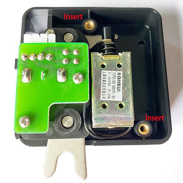
Insert Placement Methods:
Manual Placement:
●Significantly increases cycle time
●Suitable for low-volume production or complex parts
Automated Placement:
●Preferred for high-volume manufacturing
●Reduces human error
●Improves efficiency
●Shortens cycle time
●Enhances product reliability
Hybrid Performance: Combines plastic’s easy moldability and flexibility with metal’s rigidity, strength, and heat resistance to
produce robust, intricate metal-plastic integrated parts while reducing size and weight.
Electrical Functionality: Merges plastic’s insulation with metal’s conductivity to meet core electrical requirements, including
specialized needs like magnetism conduction, wear resistance, or fastening.
Enhanced Strength: Metal inserts reinforce plastic components.
Design Flexibility: Enables novel combinations of plastic with metal or other materials.
Reduced Assembly: Eliminates secondary processes (heat fusion, welding, riveting), cutting assembly time and costs.
Diverse Inserts: Accommodates metals, fabric, paper, wires, glass, wood, coils, electrical parts, or pre-molded
plastic components.
Simplified Sealing: Integrates rigid parts or rubber sealing gaskets via OverMolding, removing complex gasket alignment
and enabling automated assembly.
Tighter Tolerances: Molten plastic fills narrower gaps than press-fitting, boosting reliability and vibration resistance in end
products.
Secure Encapsulation: Proper material/process selection protects fragile inserts (glass, coils, electronics) via plastic
encapsulation.
Full Embedding: Suitable mold designs allow complete encapsulation of inserts within plastic.
Automation Compatibility: Vertical injection machines with robotics and insert feeders enable fully automated production.
Complexity & Cost: Insert placement complicates mold design, extends cycle times, raises costs, and challenges automation.
Internal Stress: Differing thermal expansion coefficients between inserts and plastic can cause cracking (notably with threaded inserts).
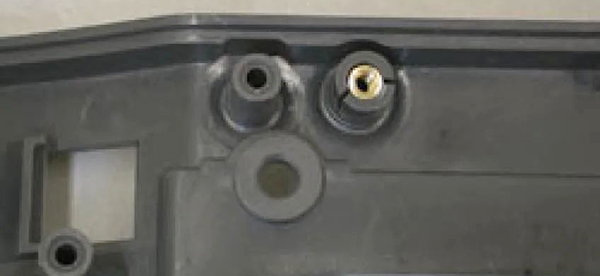
Part Warpage: Thermal expansion mismatches may induce deformation.

Pre-Processing: Inserts (especially threaded ones) often require pre-heating/drying to minimize stress.
Insert Stability: Inserts must be securely fixed in molds to prevent displacement by molten plastic flow.
High Scrap Cost: Defects (molding flaws, missing/misplaced inserts) typically scrap entire assemblies.
Recycling Challenges: Mixed materials complicate end-of-life recycling or disposal.
Insert molding finds applications across various industries including automotive, medical, electronics (particularly connectors), and others.
Insert molding design must account for process characteristics and follow Design for Manufacturing (DFM) principles. Key guidelines include:
1. Insert Material Selection
●Options: Copper, aluminum, steel, rigid dissimilar plastics, ceramics, glass, or plastic parts
●Brass recommended: Corrosion-resistant, machinable, cost-effective
2. Insert Geometry
●Prefer circular or axisymmetric shapes
●Avoid sharp corners to ensure uniform shrinkage and prevent stress concentration
3. Insert DFM
●Ensure machinability for metal inserts (machined/stamped)
4. Mold Placement
●Design protruding sections as cylindrical features for easy positioning in mold cavities
5. Sealing Structures
●Add features like sealing bosses to prevent material leakage during injection
6. Minimum Wall Thickness
●Maintain distance T > D/6 between insert base and plastic wall to avoid sink marks
7. Sidewall Clearance
●Ensure adequate spacing between inserts and sidewalls for mold strength
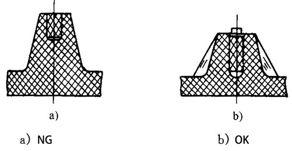
8. Boss Design
●Extend inserts to boss base (with minimum thickness)
●Radius insert heads for stability
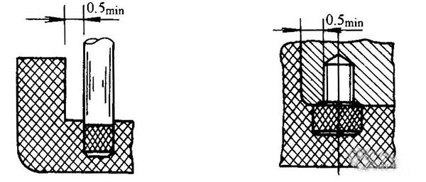
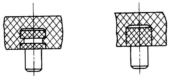
9. Small Cylindrical Inserts
●Use knurled surfaces (depth: 1-2mm) or center grooves for embedding
10. Sheet Inserts
●Secure via perforations (thickness >0.5mm) or bent tabs (thickness <0.5mm)
11. Rod Inserts
●Fix using flattened heads, notches, bends, forked ends, or mid-section crimping
12. Connector Terminal Security (Critical for electrical components)
●Terminal perforations in plastic
●Non-standard terminal shapes
●Terminal bending
●Surface roughening (dimples/protrusions)
●Increased plastic wall thickness
Contact: Roy Hwang
Phone: +86-15869559228
E-mail: info@ubetterplastic.com
Whatsapp:0086-15869559228
Add: No.78, Shipoqiao Middle Road, Yuyao City, Zhejiang Provice, China
We chat
